 |
| October 23, 2012 | Volume 08 Issue 40 |
Designfax weekly eMagazine

Archives
Partners
Manufacturing Center
Product Spotlight
Modern Applications News
Metalworking Ideas For
Today's Job Shops
Tooling and Production
Strategies for large
metalworking plants
Engineer's Toolbox:
Mold makers show designers ... This mold will work
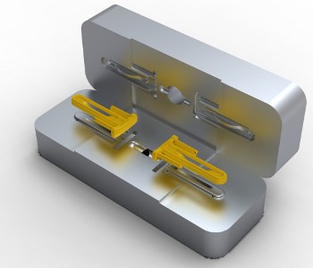
Rendered image of core and cavity models created using VISI Modelling.
Engineering polymers specialist LGG Charlesworth's work has been revolutionized by the unique prediction tool VISI Flow, which analyzes exactly how a mold will perform ahead of tool manufacture, whether it be a tool made on site or at a sub-contractor.
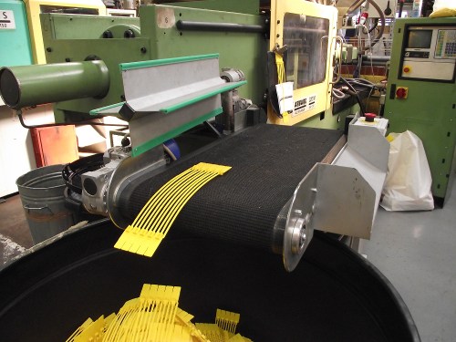
Providing total molding solutions for customers across a variety of sectors including aerospace, medical, and petro-chemical, Charlesworth (located in Worcestershire, U.K.), manages the entire project. Molding mainly engineering polymers has steered them toward the technical-products end of the market, which generally keeps volumes down. But they also manufacture millions of their own Talisman range of security/anti-tamper products and other high-volume items.
Charlesworth uses VISI Flow's innovative technology from Vero Software for injection simulation to show their network of mold-making sub-contractors exactly how the mold should be manufactured for each project.
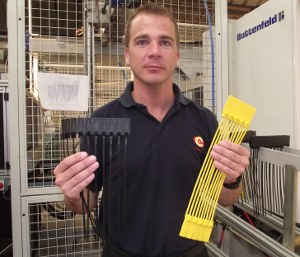
Andrew Bottomley, technical director, with molded components.
This "preventative analysis" detects a wide range of potential manufacturing issues such as warpage, weld lines, air traps, filling aspects, and hot spots, while determining the optimum gating position. Technical Director Andrew Bottomley says they generally start using it at the quotation stage, looking at the fill characteristics and cycle times, enabling them to produce accurate costings.
"When the customers place an order, we then carry out a full flow analysis to verify feeds and identify any problems with the component design, which are overcome before starting to detail the tooling," says Bottomley. He cites a recent example when VISI Flow highlighted what he describes as a "very, very low wall deviation." They showed it to the customer, then worked with them to amend the design, ensuring there was no problem when molding began. "Without VISI Flow, it wouldn't have been picked up until the molding trial, so that saved time and money immediately.
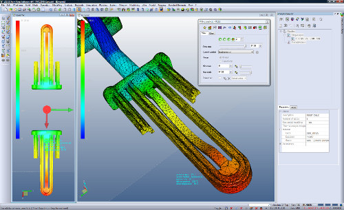
VISI Flow simulation of plastic flow front filling.
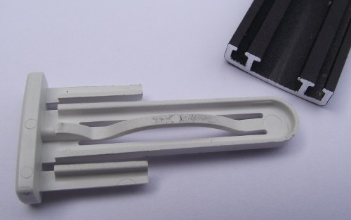
Molded component snapshot.
"Whereas the actual development cycle of an average mold used to take around eight weeks from first sample to full production, with VISI Flow this has been reduced significantly. It means that when our customers get the first molded product off the tool, it's as near to specification as possible," says Bottomley.
Bottomley says it is vital to select the correct tooling company from their network of mold makers across the U.K. and China, depending on the type of mold needed for the individual job. "But whichever mold-maker produces the tooling, they're all delighted to be given the exact specifications to work to," he says. "VISI Flow means we have more control over the tool design, so we're supporting our toolmakers to a much higher level and taking the burden away from them. They don't want tools going back for correction, and with VISI Flow we don't have to send them back."
It helped LGG Charlesworth create the perfect solution for a tool to mold an aerospace connector block with 32 multiple pitch sensor holes. Bottomley explains, "The mating parts need to line up with equipment manufactured in America or the Far East, so tolerance levels are extremely tight.
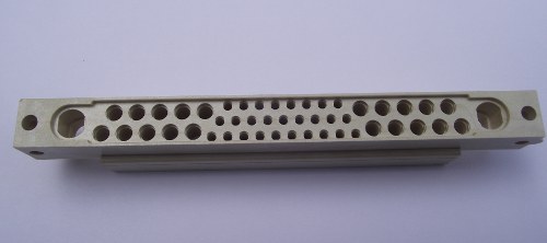
Molded aerospace connector block with 32 multiple pitch sensor holes.
"In order to manufacture something with multiple holes, the molding reacts very differently compared to general specification shrinkage. A normal shrinkage rate has perhaps .03-in. to .07-in. tolerance of shrinkage, but that varies depending on the wall section and any support structures within the molding. We were able to apply five different shrinkage values in five different areas, and we actually designed the component to have distortion. The component was distorted in a way that when it filled we knew it would be absolutely correct to the drawing. We demonstrated this in VISI Flow to the toolmaker, Paul Moore, of HDM, and he had full confidence that if he made it to our specification, based on what VISI Flow told us, it would be absolutely right."
Paul Moore would normally expect a project of this complexity to take around 30 weeks, and was delighted when it came in at 16 weeks.
Steve Kerridge, LGG Charlesworth's sales director, also uses VISI Flow as a marketing tool. "It improves our standing in the eyes of customers when we show them exactly how their product will be molded and we can raise any molding issues, especially if they provide us with a 3D model and they can see the flow analysis at the quotation stage. They feel they're much closer to the end product than if they're just given a price against a drawing."
The tools used on Charlesworth's 32 Arburg, Krauss, and Battenfeld molding machines, from 25 tons up to 160 tons, are made from a range of metals such as aluminum and fully heated tool steels.
Molded components taken from the Arburg molding machine.
VISI Flow's materials database of 7,500 polymers is particularly useful to Bottomley, as many of the engineering materials his company uses are available in it. "Also, the software's graphical representation is so easy to understand," he says.
Finalizing the venting details at the front end of manufacture is also proving invaluable. "Historically, when a mold first goes on the machine, you'd need to try at least once to work out where air entrapment occurs," says Kerridge. "But now, it's all done on computer, before the mold is made. And it makes corrective actions much more efficient. Recently, it highlighted a flow issue on a part and proved that an unusual-shaped gate was the best solution -- something we didn't anticipate."
The filling phase of the analysis provides the same level of control over the injection of molten polymer into the mold cavity as on any injection-molding machine. Moving on to the distortion calculation, the user can visualize and measure the final molded shape predicted after processing the values for filling, holding, and freezing. The thermal module considers all possible thermal effects due to the heat exchange between the molten polymer and the mold inserts with highly conductive materials. Visualization of cooling-related warpage helps define the best layout to achieve the shortest possible cycle times.
Charlesworth Managing Director Graham Ward says VISI Flow makes an excellent contribution to their technical capabilities, resolving tooling much quicker than before. "It's extremely intuitive, and its integration with CAD is absolutely seamless," he says.
Source: Vero Software
Published October 2012
Rate this article
View our terms of use and privacy policy